Todo
Link to original
- Touch base w/ Ethan on material properties
- Get the jobs running via Python scripts
- Find out how to apply a torsional displacement BC
This week
Monday
Meeting with Adrian. Not much to note last week was mostly about completing the structures assignment.
Thursday
I found out how to define a boundary condition requiring torsion using analytical fields. The field defines the distribution, and that gets scaled by the constraint you pick. So, first we start with the rotation matrices:
In Abaqus we define the two equations separately, one for horizontal and one for vertical
Now we define the fields while picking a to use. A key difference is that due to our co-ordinate system being ZY the equations look a little different


And then we apply these analytical fields to the stretch nodes:
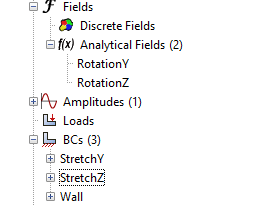
There was more boundary conditions added, such as setting the node rotation on torsion to as well as fixing the other DOF (U1, UR2, UR3).
There was some difficulty, namely with making sure co-ordinate systems and displacements were correct. One funny thing I couldn’t understand was why my whole model was rotating, and that was because I had temporarily disabled the wall BC. Unfortunately wasted half an hour on that, thinking it was a buckling issue (as I was getting negative eigenvalue errors).
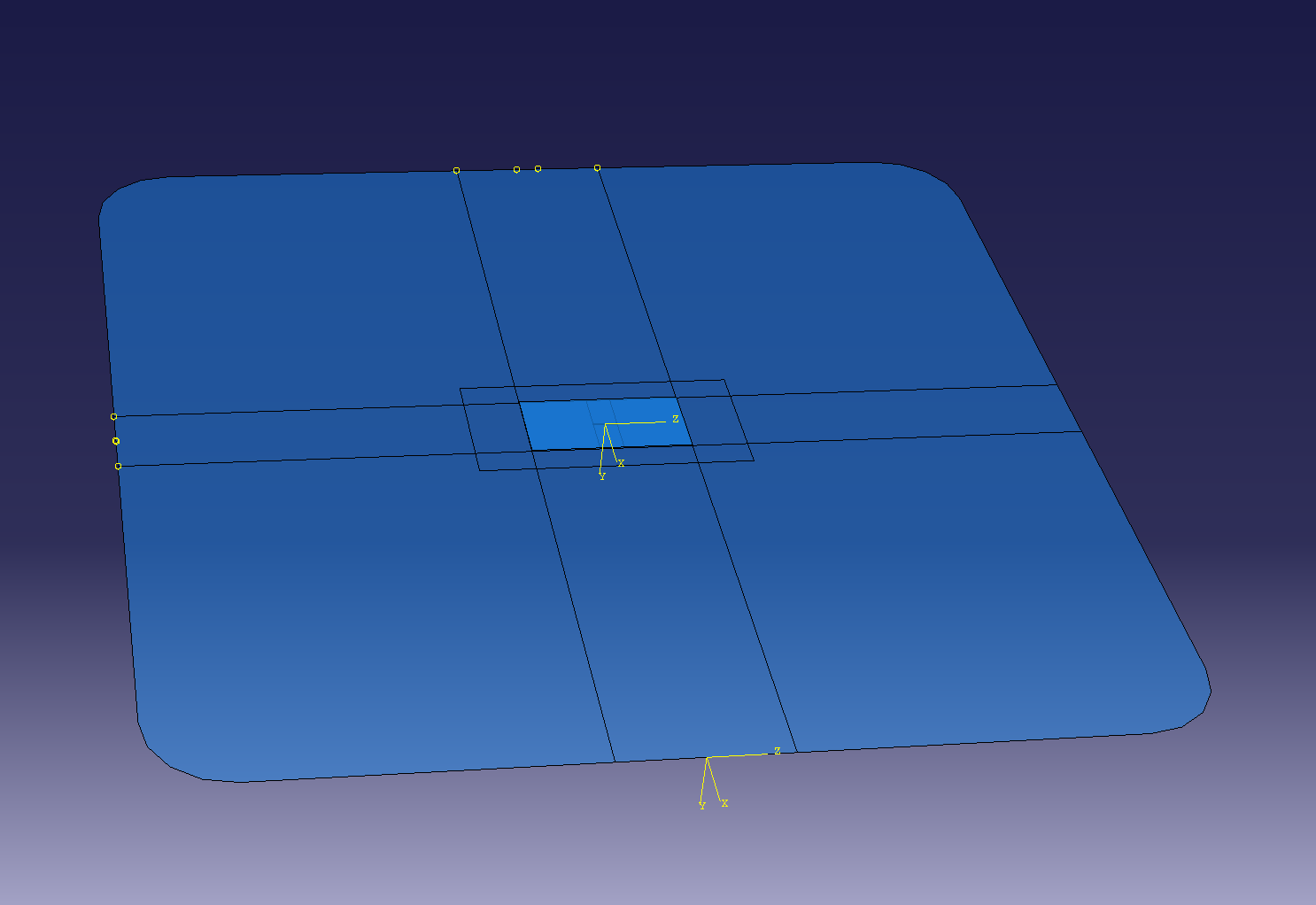
Eventually, the torsion worked out alright:
Currently exact adhesive values are still being found by other group members
Since this is a displacement load, it’s not the actual torsional moment being applied. That can be done by looking at the reaction forces and moments. In fact, you can define a derived field output based on the reaction force RF and reaction moments RM at a node.
Friday
Remodelling
For Friday, the main focus was to remodel the mesh to actually be more indicative of a patch repair. The shape of the surface was modified to be a square and a 10x20 patch was created to sit over the 3mm crack.
Adaptive meshing
In order to remove errors in stress calculation, I remeshed the surface and patch to make the patch corner stresses more realistic, as well as better model the stress around the crack. The adhesive could not be remeshed as Abaqus only supports remeshing tri and quad elements, but the patch remeshing and stresses gave insight into how the adhesive mesh would experience stresses.
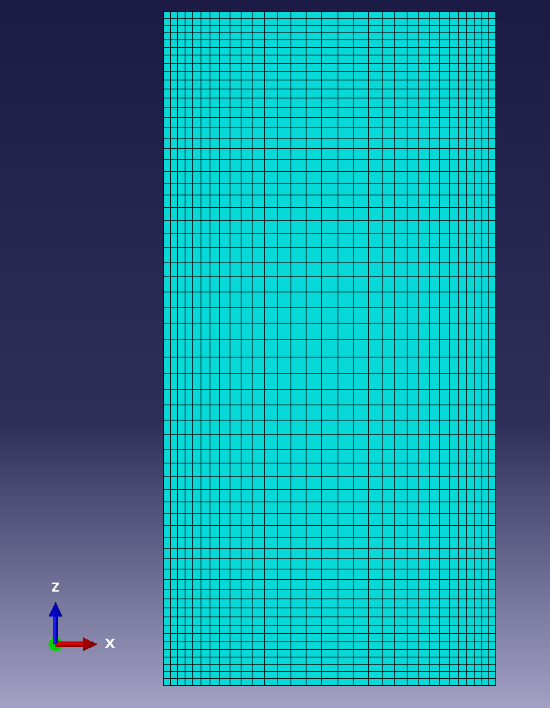
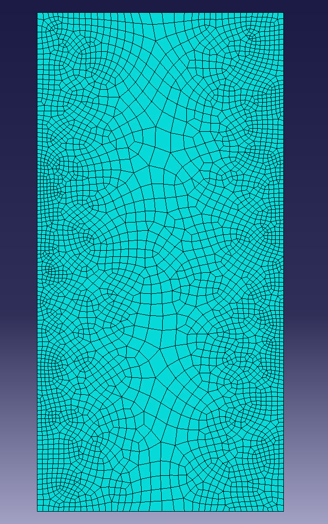
^ Patch before and after remeshing
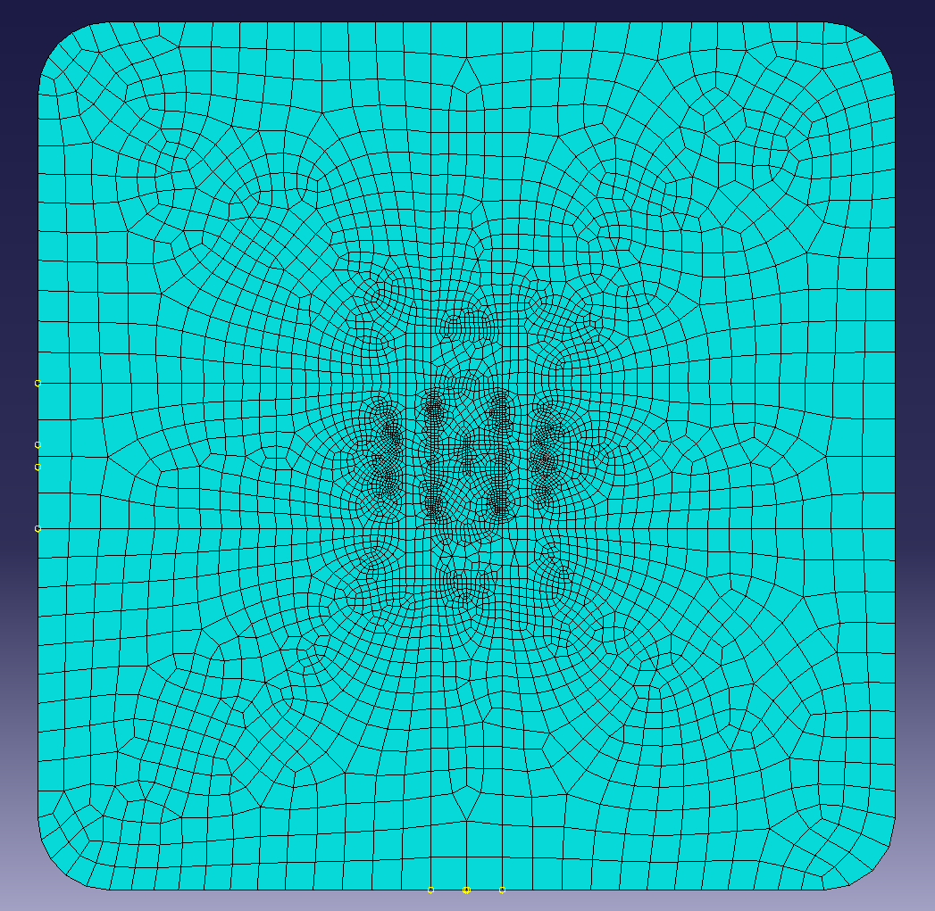
During the remeshing process, it was found that the sharp corners of the initial mesh were carrying unrealistic stresses and so these corners were rounded and the remeshing was done again. Another change was changing the loading from twisting (which would be non-symmetrical) to pure tension. This would still have similar stress concentrations to the torsional case but would make sure the remeshing would be relatively symmetrical.
What I learnt
- You can create basically any positional constraints by using an analytical field.
- You can operate on field values to create new field values (RF, U, and RM to give total rotational moment)
- You can’t really use an adaptivity process to decrease the number of elements, only increase.]
Todo
- In Python:
- Run a single job
- Put at least one result we want in a different object database so we can compare stuff from multiple runs
- Follow up on material values w/ Ethan