2D lap joint -> 3D lap joint (still isotropic adherends)
Monday
Meeting w supervisor.
Thursday
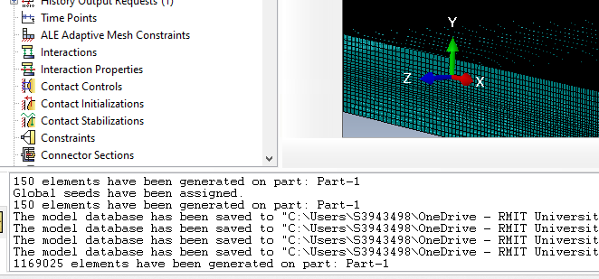
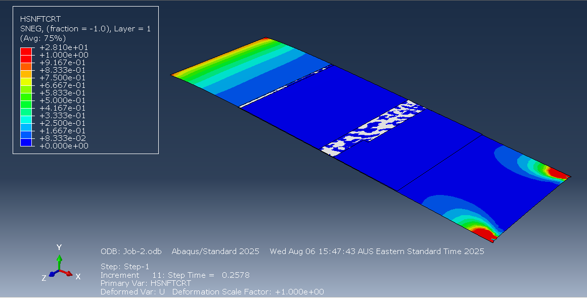
Creating a 3D lap joint model (currently with isotropic adherends). Got better at seeding the mesh edges. Initially the mesh was way too fine.
I later fixed this to have less elements.
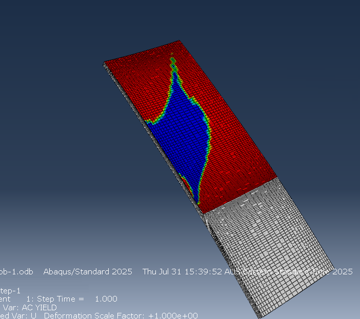
Here it also shows where the adhesive has yielded. This is with an eccentric load downwards and to the left. Next step is to make the adherends composite materials.
What I learnt
Don’t create a mesh with over a million elements.
Modelling the 3D case is very similar it’s just that you extrude the original sketch
You can easily seed the edges by setting the view to partially transparent and dragging, as opposed to trying to click them
It’s really hard to set the correct force in an Abaqus/Explicit model without damage modelling because if it’s too much end exceeds the adhesives ultimate strength it wants to just extend forever.
Todo
Composite adherends
Discuss with team what the loading shape should be
Meeting w/ Adrian. He said we should work towards having a theme of repair. This makes me think that moving towards a plug repair would be good. Ethan will have to change the numbers around for some of the single axis loading hand calcs but that should be fine.
Wednesday
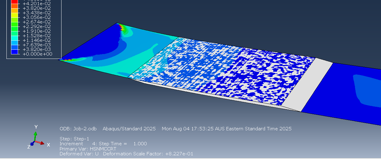
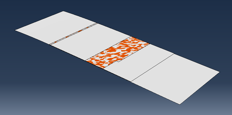
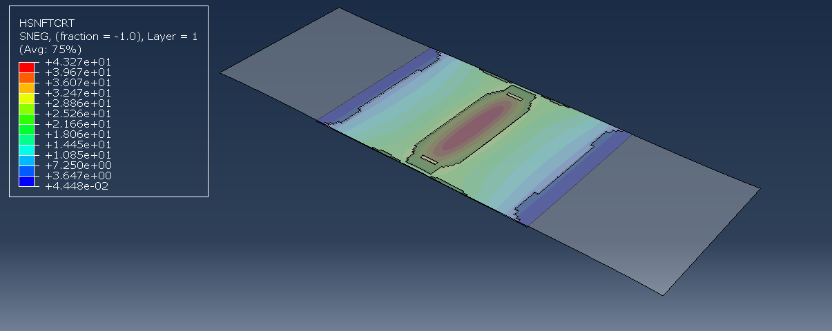
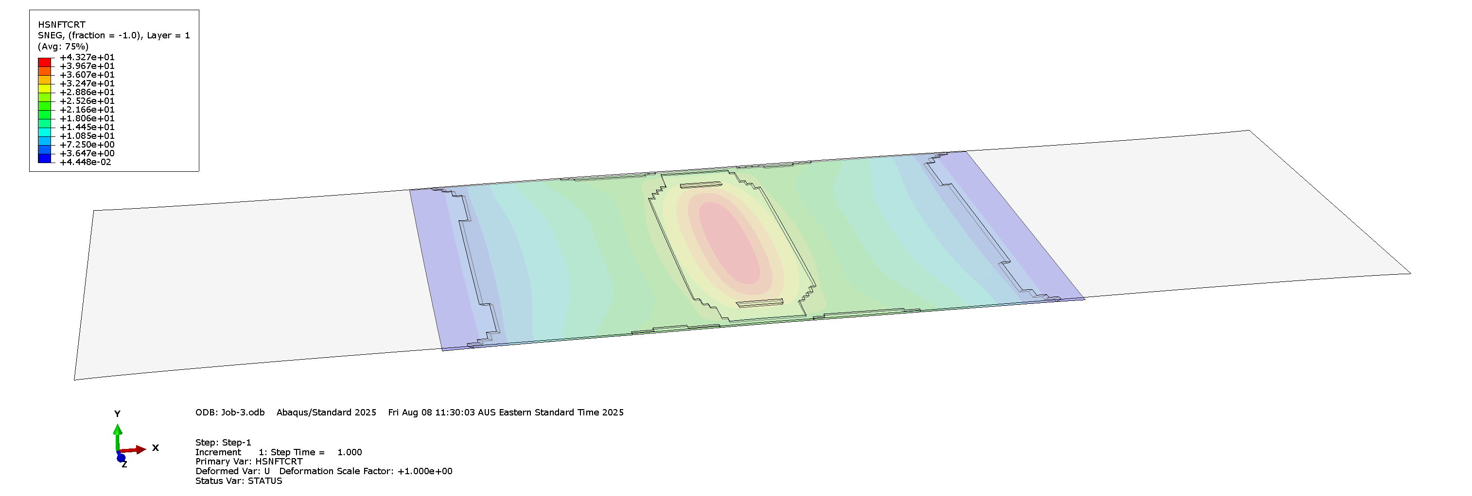
Got composite adherend for the lap joint model. This one is a different model because it uses shells for the composites instead of the 3d elements. The composite follows the Hashin Criterion and shows when the fiber or matrix fails either from compression or tension (as shown below, where it’s showing the fibre tensile failure criterion). The composite doesn’t have damage evolution but that’s okay. The adhesive is modelled with cohesive elements.
Also, the force comes from the displacement of the end instead of applying a direct edge load. This is way better because it doesn’t lead to infinite stretching. In the photo above, the adhesive isn’t deleting even though I applied a damage criterion based on max stress, which is addressed later.
The adhesive damage and deletion is also working. I realised that the issue was that I hadn’t applied a mesh stacking direction nor a material orientation to the cohesive elements.
Thursday
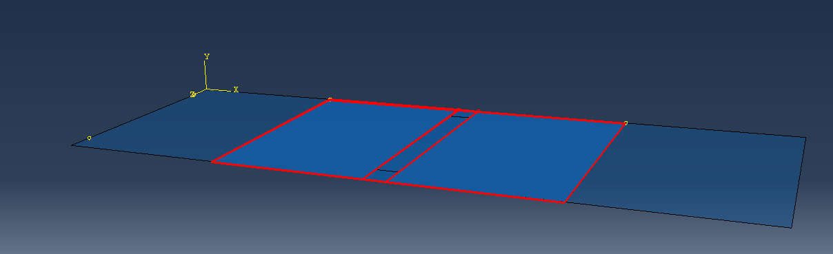
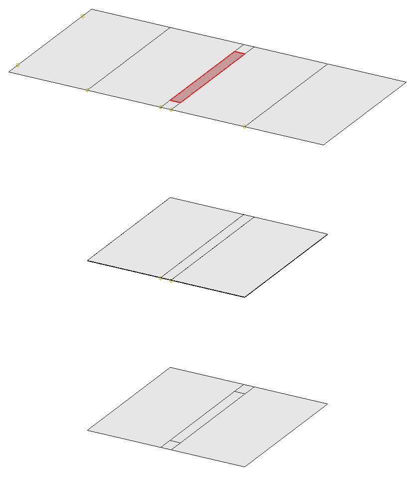
I took the learning from the lap joint model and used it to make a scarf joint. First I modelled the damaged surface (aluminum) with a shell:
The part in the center is weakened by making the young’s modulus only 10% of what it was before. I will have to confirm with Jalisha to make sure this is the best way to do it. Then I made an adhesive layer (cohesive elements) and tied that to the surface. The cohesive elements need definitions for traction based separation. I tied a composite shell to the adhesive layer underneath to act as the patch.
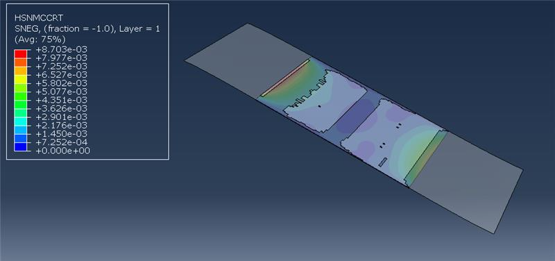
Here is the right edge being pulled down:
And the right edge being pulled out:
It makes sense that the adhesive fails in the middle as that is where the material is weakest.
Right now the material properties just use magic numbers. Ethan will be filling in the material data eventually but I can keep working with the values I have now and change them later.
Friday
Created a document that we can put the material properties in. It’s just looking at what Abaqus needs and representing it in a way that allows us to easily reference it later.
Working on the completion plan diagram. I’ve been making it in Microsoft Visio because it has teams integration so it’s the easiest to work with.
I’ve discussed the plan with Ethan and he seems happy with it for the most part it just comes down to getting the details from the scarf repair side, as well as finalising who will do what in the second half of the semester.
What I learnt
One way to define adhesives is to use cohesive elements that have a traction definition. You must define the mesh stack direction and material orientation. Then you have to define the elasticity in terms of traction. For damage, you’ll also have to define damage criterion. For deletion, you’ll have to specify damage progression as a sub-property.
When you’re running jobs so many times, just make a coarser mesh initially and then worry about making it finer later.
Microsoft Visio kinda sucks. The arrows are very unintuitive. I would’ve preferred excalidraw but no Teams integration.
Todo
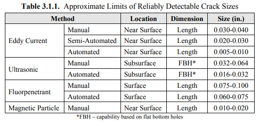
Confer with Jalisha to get the actual dimensions for the damage
Meeting with Adrian. He’s happy with the fact that we’re assigning/micromanaging tasks more.
Jalisha and I finalised that the crack length should be 3mm
Source
We have yet to finalise material properties but that can come later as it’s just a matter of changing numbers in Abaqus.
We have also decided to try to do as much of the report as possible before the poster because then making the poster is just a matter of summarising existing information :3
Tuesday
We have confirmed that the modelled surface will be 5 x 50 x 15 (depth) mm for the sake of having consistent analyses.
Wednesday
I added some information on the modelling of the patch repair to the completion plan introduction.
Thursday
Finalising completion timeline by adding in the tasks that Jalisha, Sam and Mitch will do for the scarf repair.
Sunday
Proofreading completion plan and adding patch repair info to the Completed Tasks part.
I can do a displacement load based off a normal co-ordinate system but not for a cylindrical system (which I wanted to use so that I can apply a torsional displacement). It gives an error for having elements on the rotational axis itself right now so maybe a rotation would have to be define through a script or some other method (like just rotating the corner nodes).
Meeting with Adrian. Only caught the end of it because I slept in. Overall he’s happy with the report (besides formatting)
Wednesday
Been working on python scripts for the model. Right now I’m getting a bit confused over what I can do in Abaqus/CAE vs the Abaqus kernel, but overall I have a VSCode environment working using the Abaqus API, which gives good typing information https://pypi.org/project/pyabaqus/. So far I’ve just been learning the environment and tinkering with existing scripts. The script below is modified to give more field values such as the plastic strain as well.
Max Mises Stress Script
VonMisesPy
import mathfrom odbAccess import openOdb, Odbfrom abaqus.Odb.FieldValue import FieldValuefrom sys import argv, exitdef rightTrim(input, suffix): if input.find(suffix) == -1: input = input + suffix return inputfrom dataclasses import dataclassfrom typing import Any, Callable, Generic, Optional, Tuple, TypeVar@dataclassclass StepFrame: stepName: str step: Optional[int] frame: int def __str__(self) -> str: return f'"{self.stepName}" (S{self.step}) F{self.frame}' def __hash__(self): return hash((self.stepName, self.frame))@dataclassclass DataPoint: fieldValue: FieldValue element: Optional[int] node: Optional[int] def __str__(self) -> str: return f"{self.fieldValue} in element #{self.element}"FieldComparisonCallable = Callable[[FieldValue], float]def getMaxFieldValue( odb: Odb, elsetName: Optional[str], fieldOutputName: str, fieldComparisonKey: FieldComparisonCallable,) -> dict[StepFrame, Optional[DataPoint]]: """Print max mises location and value given odbName and elset(optional) """ assembly = odb.rootAssembly # process the element subset if elsetName: if elsetName in assembly.elementSets: elemset = assembly.elementSets[elsetName] else: raise ValueError( "An assembly level elset named %s does" "not exist in the output database %s" % (elsetName, odbName) ) else: elemset = None isFieldPresent = False maxFieldKey = -float("inf") maxFieldValues = {} for stepName, step in odb.steps.items(): print("Processing Step:", step.number) for frame in step.frames: stepFrame = StepFrame(stepName, step.number, frame.incrementNumber) frameMaxValue: Optional[DataPoint] = None frameFields = frame.fieldOutputs if fieldOutputName in frameFields: isFieldPresent = 1 fieldOutput = frameFields[fieldOutputName] if elemset: fieldOutput = fieldOutput.getSubset(region=elemset) fieldValueArray = fieldOutput.values if fieldValueArray is None: continue for fieldValue in fieldValueArray: fieldKey = fieldComparisonKey(fieldValue) if fieldKey > maxFieldKey: maxFieldKey = fieldKey frameMaxValue = DataPoint( fieldValue=fieldValue, element=fieldValue.elementLabel, node=fieldValue.nodeLabel, ) maxFieldValues[stepFrame] = frameMaxValue # end for frame if not isFieldPresent: raise ValueError("No field present in element set") return maxFieldValuesif __name__ == "__main__": odbName = None elsetName = None argList = argv argc = len(argList) i = 0 while i < argc: if argList[i][:2] == "-o": i += 1 name = argList[i] odbName = rightTrim(name, ".odb") elif argList[i][:2] == "-e": i += 1 elsetName = argList[i] elif argList[i][:2] == "-h": print(__doc__) exit(0) i += 1 if not (odbName): print(" **ERROR** output database name is not provided") print(__doc__) exit(1) odb = openOdb(odbName) fieldComparisonKey: FieldComparisonCallable = ( lambda fv: fv.mises if fv.mises is not None else math.nan ) try: maxMisesValues = getMaxFieldValue(odb, elsetName, "S", fieldComparisonKey) for stepFrame, maxMisesPoint in maxMisesValues.items(): value = None if maxMisesPoint is not None: value = fieldComparisonKey(maxMisesPoint.fieldValue) print(f"at {stepFrame}: Max Von Mises Stress = {value}") except Exception as e: print(e) fieldComparisonKey: FieldComparisonCallable = lambda fv: fv.data[0] try: maxMisesValues = getMaxFieldValue(odb, elsetName, "PE", fieldComparisonKey) for stepFrame, maxMisesPoint in maxMisesValues.items(): value = None if maxMisesPoint is not None: value = maxMisesPoint.fieldValue.data print(f"at {stepFrame}: Max Plastic Strain = {value}") except Exception as e: print(e) odb.close()
Meeting with Adrian. Not much to note last week was mostly about completing the structures assignment.
Thursday
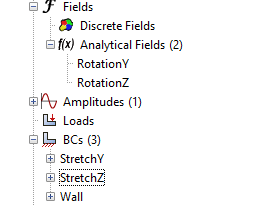
I found out how to define a boundary condition requiring torsion using analytical fields. The field defines the distribution, and that gets scaled by the constraint you pick. So, first we start with the rotation matrices:
In Abaqus we define the two equations separately, one for horizontal and one for vertical
ΔxΔy=x(cosθ−1)−ysinθ=x(sinθ)+y(cosθ−1)
Now we define the fields while picking a θ to use. A key difference is that due to our co-ordinate system being ZY the equations look a little different
And then we apply these analytical fields to the stretch nodes:
There was more boundary conditions added, such as setting the node rotation on torsion to θ as well as fixing the other DOF (U1, UR2, UR3).
There was some difficulty, namely with making sure co-ordinate systems and displacements were correct. One funny thing I couldn’t understand was why my whole model was rotating, and that was because I had temporarily disabled the wall BC. Unfortunately wasted half an hour on that, thinking it was a buckling issue (as I was getting negative eigenvalue errors).
Eventually, the torsion worked out alright:
Currently exact adhesive values are still being found by other group members
Since this is a displacement load, it’s not the actual torsional moment being applied. That can be done by looking at the reaction forces and moments. In fact, you can define a derived field output based on the reaction force RF and reaction moments RM at a node.
Friday
Remodelling
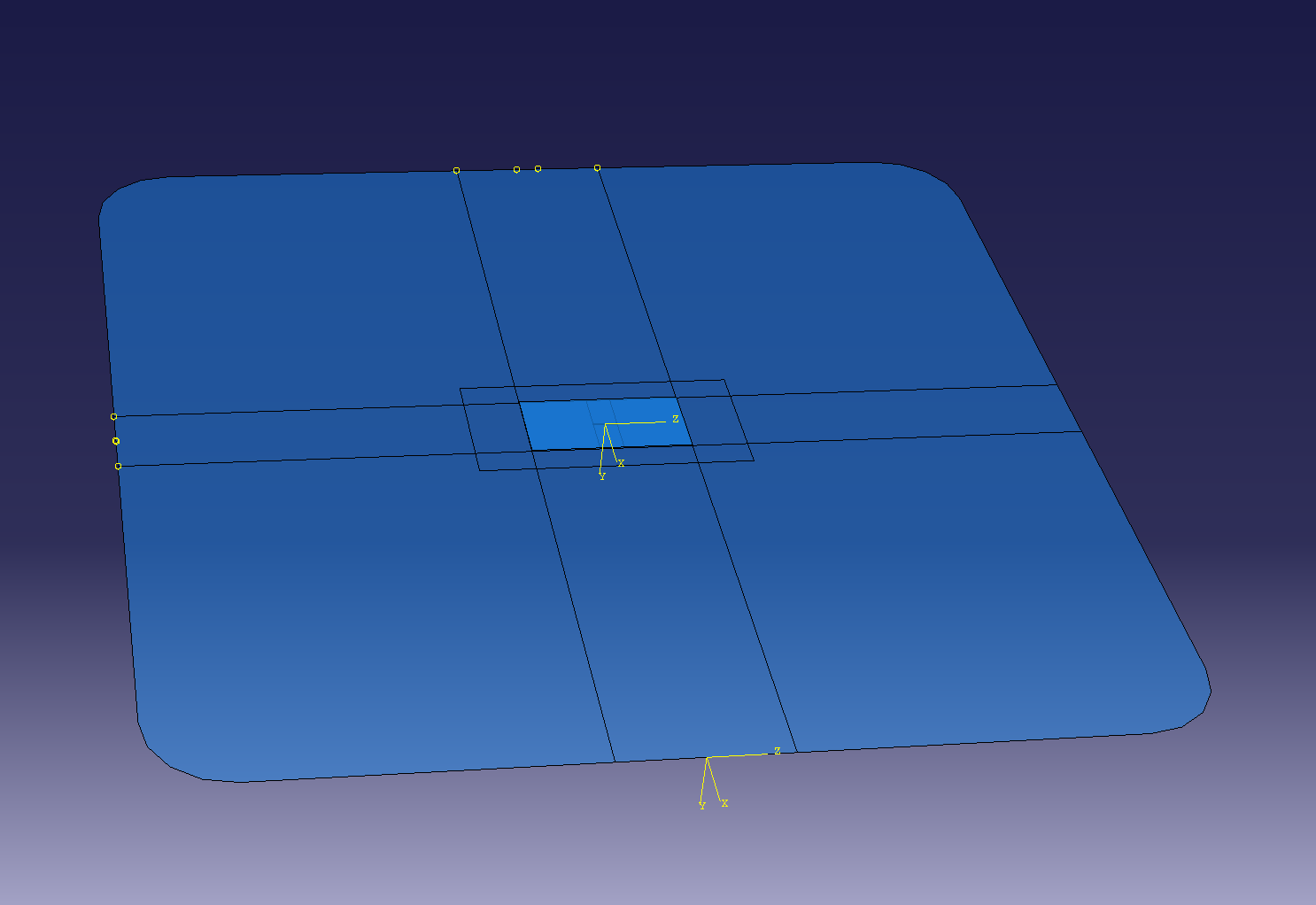
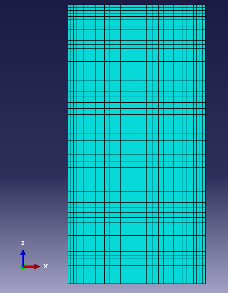
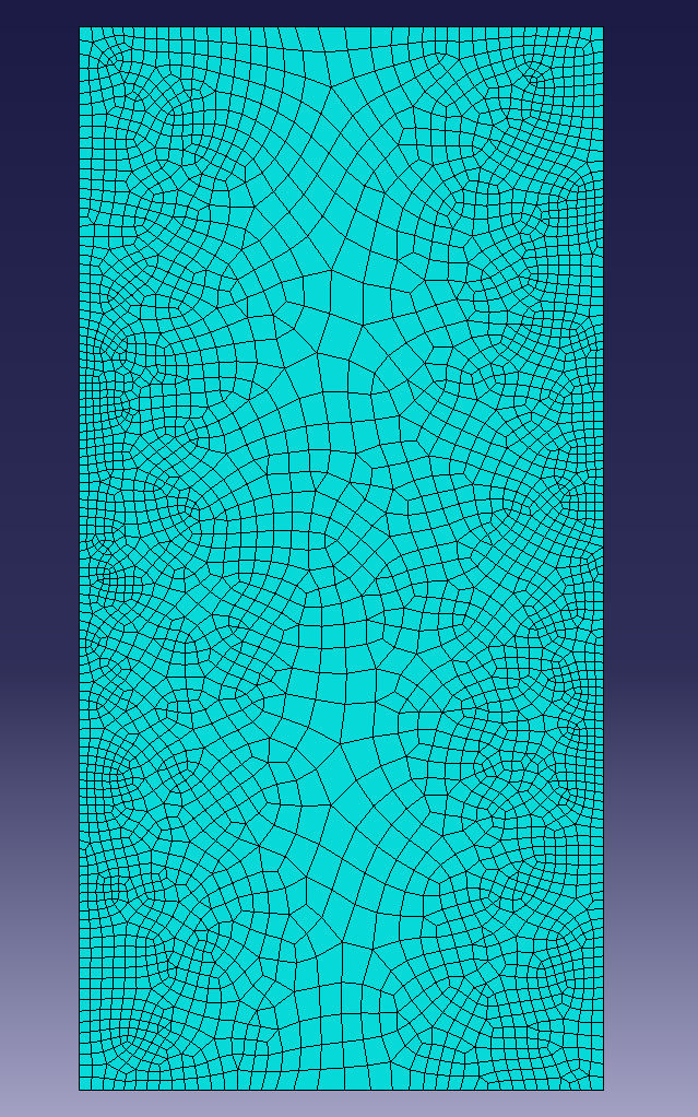
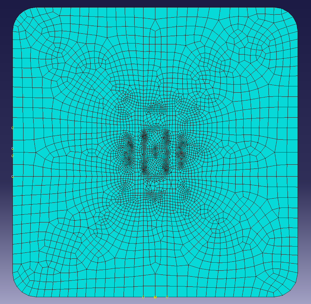
For Friday, the main focus was to remodel the mesh to actually be more indicative of a patch repair. The shape of the surface was modified to be a square and a 10x20 patch was created to sit over the 3mm crack.
Adaptive meshing
In order to remove errors in stress calculation, I remeshed the surface and patch to make the patch corner stresses more realistic, as well as better model the stress around the crack. The adhesive could not be remeshed as Abaqus only supports remeshing tri and quad elements, but the patch remeshing and stresses gave insight into how the adhesive mesh would experience stresses.
^ Patch before and after remeshing
During the remeshing process, it was found that the sharp corners of the initial mesh were carrying unrealistic stresses and so these corners were rounded and the remeshing was done again. Another change was changing the loading from twisting (which would be non-symmetrical) to pure tension. This would still have similar stress concentrations to the torsional case but would make sure the remeshing would be relatively symmetrical.
What I learnt
You can create basically any positional constraints by using an analytical field.
You can operate on field values to create new field values (RF, U, and RM to give total rotational moment)
You can’t really use an adaptivity process to decrease the number of elements, only increase.]
Todo
In Python:
Run a single job
Put at least one result we want in a different object database so we can compare stuff from multiple runs
I inputted the new material values for the aluminium, adhesive, and patch. The adhesive is now using significantly stronger values, which makes sense as an adhesive needs to be strong.
After doing this, I’m focusing on making scripts that can help me run tests and extract information. A significant portion of this time was just getting a simple working script for extracting odb information easily. I am making many mistakes but I am also learning many things, which is a plus.
After finally setting up a good way to get position (COORD), displacement (U/UR), and force (RF/RM) values for the wall and stretch positions, I can now use the nodal values at the stretch location to get specific useful values:
# for each frame:tension = -sum(val.data[0] for val in fieldOutputs["RF"])stretch = statistics.mean(val.data[0] for val in fieldOutputs["U"])elongation = stretch / GEOMETRY["Length"]
From this I can then start getting values of crack stress vs applied tensile stress:
What I learnt
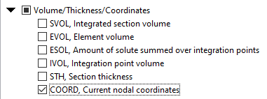
You can also specify a COORD field output to get the integration point original positions
With FEA, some field outputs are at nodes, whereas some are at elements. The sets for these are different. You cannot get displacements (U) on element sets; you must use node sets.
You can use the Abaqus/CAE kernel line to easily sandbox things before putting them in code
>>> step.frames[0].fieldOutputs["COORD"].values[0].dataarray([-5. , -0.075 , 9.799999], dtype=float32)>>> step.frames[0].fieldOutputs["COORD"].getSubset(wallSet)TypeError: arg1; found OdbSet, expecting UNDEFINED_POSITION, NODAL, ELEMENT_NODAL, INTEGRATION_POINT, ELEMENT_FACE_INTEGRATION_POINT, WHOLE_ELEMENT, WHOLE_REGION, WHOLE_MODEL, CENTROID, SURFACE_INTEGRATION_POINT, SURFACE_NODAL, ELEMENT_FACE or WHOLE_PART_INSTANCE>>> step.frames[0].fieldOutputs["COORD"].getSubset()openOdb(r'C:/Users/.../Twist.odb').steps['Step-1'].frames[0].fieldOutputs['COORD'].getSubset()>>> step.frames[0].fieldOutputs["COORD"].getSubset(region=wallSet)openOdb(r'C:/Users/.../Twist.odb').steps['Step-1'].frames[0].fieldOutputs['COORD'].getSubset(region=openOdb(r'C:/Users/.../Twist.odb').rootAssembly.elementSets['WALL'])>>> wallOutputs = step.frames[0].fieldOutputs["COORD"].getSubset(region=wallSet)>>> wallOutputs.valuesopenOdb(r'C:/Users/.../Twist.odb').steps['Step-1'].frames[0].fieldOutputs['COORD'].getSubset(region=openOdb(r'C:/Users/.../Twist.odb').rootAssembly.elementSets['WALL']).values>>> wallOutputs.values[0].dataarray([-58.564137, 0. , -47.995377], dtype=float32)>>> wallOutputs = step.frames[0].fieldOutputs["U"].getSubset(region=wallSet)>>> wallOutputs.values[0].dataIndexError: Sequence index out of range
Small gap between updates. Many things were done, such as:
Developing Python code to create the input files.
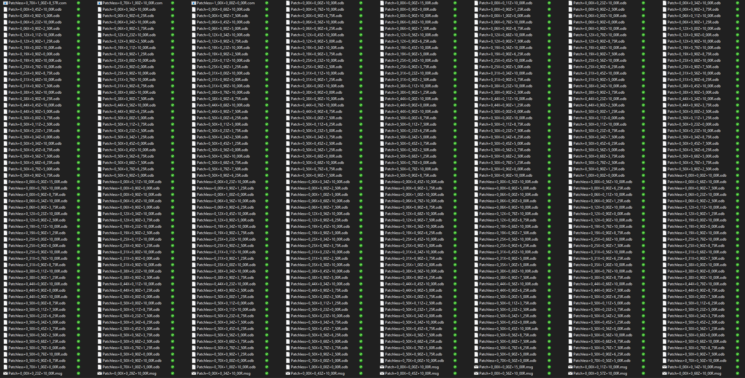
Developing Python code that could run all the jobs in a batched way
Developing python code to read the ODBs and get key information
Use that information in MATLAB to then get more data.
Develop Python code to get the contour images for me (Why do something repetitive for 2 hours if I can just spend a mere 6 hours automating it)
Actual analysis of results
I ended up creating 434 jobs, which took over ~10 hours to run
I’m simply going to embed some files here and some in the pdf I’ll submit, such as the matlab code.