Under Construction
This page is still unfinished. This is because I’m still catching up with the current state of the project and also the project isn’t actually done yet.
Overview
This is a recap of the capstone project I did along with 4 other group members. We completed this over the course of the 2025 university year (two semesters). Here I have detailed the steps we took, challenges we faced, and things I feel I have learnt over the course of this project.
Some of the struggles we encountered were:
- Having a group member drop out during the project
- Having to work around busy schedules
- Having to change scope after assessor feedback
Some of the key takeaways were:
- How to effectively communicate in a team (in an online environment)
- How to stay organised and plan while considering other’s strengths and weaknesses
- How to deal with a change in scope for a project
- How to model a 3D component with multiple different complex parts (composites and adhesives) with failure and damage criterion.
Why did you pick this capstone project?
Because is was about modelling with FEA and that’s something I was already interested in. It also meant that I could strengthen my skills in this area by learning about how to create 3D models of composite structures
Background
“Damage Growth in Aircraft Composites Under Multi-Axial Loading Conditions”
This was the prompt given for our capstone project. This project was created in order to create potential loading cases for the multi-axial loading rig created by DSTG. The rig has can apply the loads of todo. The idea is that we can model the damage growth and then (potentially) DSTG can decide to do the actual testing of damage growth. Also, the project itself focused on analysis besides damage growth as it would still be useful.
Why do we need to do finite element analysis on components? aren't hand calculations enough?
While hand calculations can help, composite materials like CFRP are anisotropic and have complex internal structure and so do not have predictable stress concentrations nor failure modes. This means that, for example, while calculations at the element level are possible on a lap joint with aluminium adherends, the same can’t be said for a similar lap joint with composite adherends.
The diagram below highlights how, for composite materials, the physical testing and simulations are essential before testing the main structure. The configuration space for composite elements is massive, and slightly changing properties can require more testing. This is good for people studying composite materials cause we’re probably not going to run out of possible research soon.
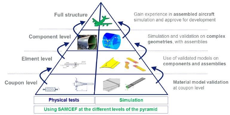
The image above shows system testing levels. First data on the coupons (testing delamination strength and other material properties) must be done and then more sophisticated elements and components can be create. Source: Damage modeling of laminated composites: Validation of the intra-laminar law of SAMCEF at the coupon level for UD plies
Timeline
Project Proposal
We had difficulty finding direction initially. Our supervisor encouraged us to focus on 3-4 projects on out own and work on them individually or in pairs. Our initial configuration were:
| Configuration | Analysis | Assignee |
|---|---|---|
| Lap Joint | Fatigue strength | Inaya (me) |
| Plug Repair | Damage tolerance | J. |
| Flat Plate with Impact | Damaged strength | E. + L. |
| Flat Plate | Delamination toughness | S. + M. |
When assigning sections for this tasks, I was given the literature review. I didn’t realise that most of the project was meant to be literature review, so I only spent ~8 hours maybe finding out about stuff for it. When we got the report back, one of the big points of feedback was that there wasn’t nearly enough literature review done. This meant we had to change a few things for the upcoming end of term report, namely distributing the literature review more. After this project, L. stop contributing to the project despite multiple emails and messages. Because of this we eventually removed them as a group member.
If I were to do this again, I would’ve worked with the team to assign more people to the literature review. This is something that was changed in the progress report, which had a lot more team contribution on the literature review.
Progress Report
Report Writeup
The time between the initial proposal and progress report was approximately 2-3 months. In this time, I focused on doing more literature review on lap joints, as well as actually modelling a lap joint. I had decided that my main focus would be looking at composite fatigue and so I found a significant number of articles which looked at testing the fatigue strength of lap joints. This wasn’t too taxing because I have a good system for using Endnote with Word and downloading citations, meaning that after reading an article I can easily download the citation, inline it where needed and have it show up at the end of the article. During this time I also focused on modelling the lap joint configuration. Overall, out literature review ended up covering:
- Types of Composite Materials
- Composite Fatigue
- Delamination
- Rivets and Bolts
- Lap Joints (my configuration)
- Scarf repairs (as this was the type of plug repair)
Lap joint modelling
While we moved away from the lap joint in Capstone B, it taught me many modelling skills. I improved on many key skills for modelling in Abaqus and in general
todo!()
General description of lap joint model and it’s purpose.
Partitioning and Meshing
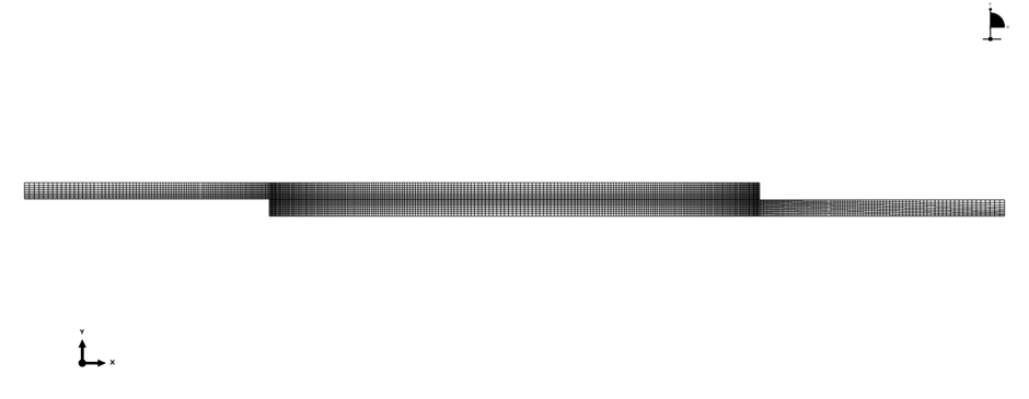
I learnt how to partition and set edge biases for a part in Abaqus. The edge seeding is important as we want to have a higher definition mesh in areas of high stress concentration (e.g the ends of the adherends) as those areas will damage more. It’s also important because we want to make sure that the adhesive layer is only 1 element thick. You can seed by element size or number.
Inelastic Material definition
I learnt how to define different stress-strain curve assumptions for different materials. For the isotropic adherends, I had to only define the Young’s Modulus and Poisson Ratio . For the adhesive, the main analysis we did was the impact of the type of adhesive used when under a tension loading. As such, three different models with different stress-strain curves in Abaqus were used: