- Capstone Project logbook (@2025-W32-D7 23:54)
Todo
- Composite adherends
- Discuss with team what the loading shape should be
This week
Monday
Meeting w/ Adrian. He said we should work towards having a theme of repair. This makes me think that moving towards a plug repair would be good. Ethan will have to change the numbers around for some of the single axis loading hand calcs but that should be fine.
Wednesday
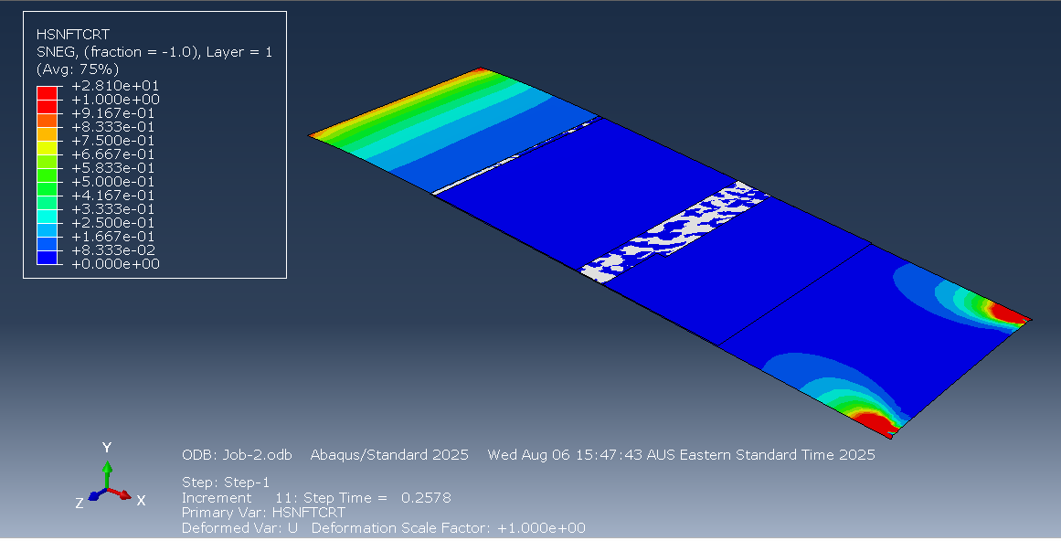
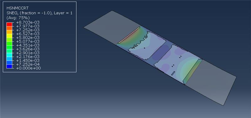
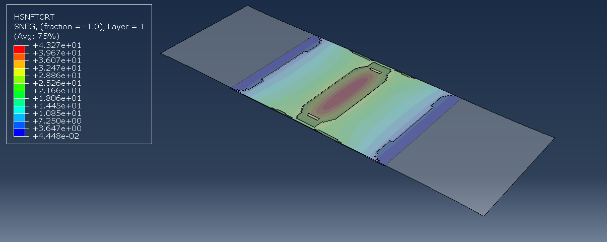
Got composite adherend for the lap joint model. This one is a different model because it uses shells for the composites instead of the 3d elements. The composite follows the Hashin Criterion and shows when the fiber or matrix fails either from compression or tension (as shown below, where it’s showing the fibre tensile failure criterion). The composite doesn’t have damage evolution but that’s okay. The adhesive is modelled with cohesive elements.
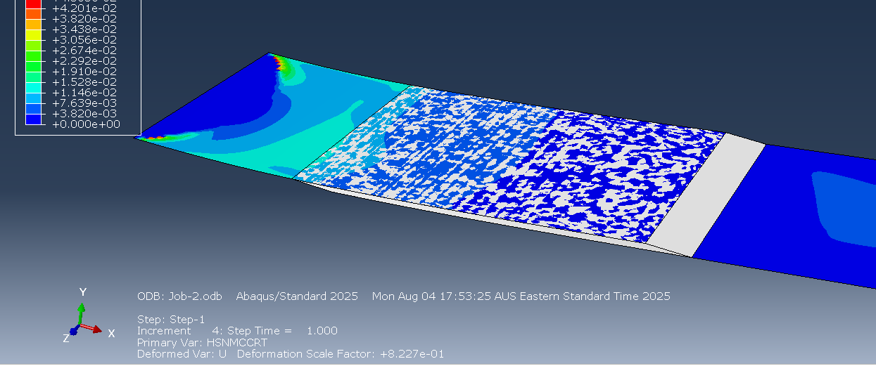
Also, the force comes from the displacement of the end instead of applying a direct edge load. This is way better because it doesn’t lead to infinite stretching. In the photo above, the adhesive isn’t deleting even though I applied a damage criterion based on max stress, which is addressed later.
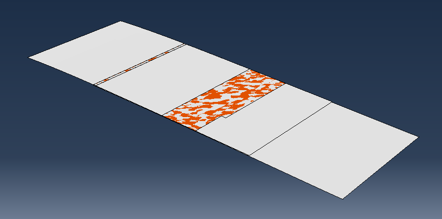
The adhesive damage and deletion is also working. I realised that the issue was that I hadn’t applied a mesh stacking direction nor a material orientation to the cohesive elements.
Thursday
I took the learning from the lap joint model and used it to make a scarf joint. First I modelled the damaged surface (aluminum) with a shell:
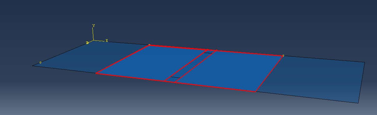
The part in the center is weakened by making the young’s modulus only 10% of what it was before. I will have to confirm with Jalisha to make sure this is the best way to do it. Then I made an adhesive layer (cohesive elements) and tied that to the surface. The cohesive elements need definitions for traction based separation. I tied a composite shell to the adhesive layer underneath to act as the patch.
Here is the right edge being pulled down:
And the right edge being pulled out:
It makes sense that the adhesive fails in the middle as that is where the material is weakest.
Right now the material properties just use magic numbers. Ethan will be filling in the material data eventually but I can keep working with the values I have now and change them later.
Friday
Created a document that we can put the material properties in. It’s just looking at what Abaqus needs and representing it in a way that allows us to easily reference it later.
Working on the completion plan diagram. I’ve been making it in Microsoft Visio because it has teams integration so it’s the easiest to work with.
I’ve discussed the plan with Ethan and he seems happy with it for the most part it just comes down to getting the details from the scarf repair side, as well as finalising who will do what in the second half of the semester.
What I learnt
- One way to define adhesives is to use cohesive elements that have a traction definition. You must define the mesh stack direction and material orientation. Then you have to define the elasticity in terms of traction. For damage, you’ll also have to define damage criterion. For deletion, you’ll have to specify damage progression as a sub-property.
- When you’re running jobs so many times, just make a coarser mesh initially and then worry about making it finer later.
- Microsoft Visio kinda sucks. The arrows are very unintuitive. I would’ve preferred excalidraw but no Teams integration.
Todo
- Confer with Jalisha to get the actual dimensions for the damage
- Try to run the jobs with python